
The Mystery of the Bad Data Line
September 19, 2025Today, I want to tell you a story of diagnostics, and a solution to a bug that made me understand a bit more about how electricity works.
I had a strand of individually addressible LEDs which unexpectedly stopped working. As I moved from breadboard with jumper cables to a soldered circuit board, the color patterns that I had programmed into the LEDs were suddenly replaced with solid white at maximum brightness.
A long-running project
Two years ago, I concieved of a project of a set of decorative safety lights on my bike. While running normally, they show one of the color patterns that I programmed in. However, I also have handlebar buttons that activate a blinker patterns, and magnetic sensors on the brake handles that activate a solid red brake light.
I spent about three days programming the project, covering the core logic, a GUI simulator that let me work out all of the animations on my desktop, and the program that could run on the hardware.
Implementing the hardware circuits took quite a bit longer, but I was able to attach the project to my bike and take it to the Providence Bike Jam.
After a few bike rides, vibration broke some of the solder joins. I took this as an opportunity to redesign the circuit board. This process went well until I encountered this bug.
The Bug
As I said before, this bug manifested while I was moving from breadboard to soldered circuit board. Before I soldered the last component into place, the lights all showed the colors I expected them to. Once I was done soldering the component into place, the lights simply showed solid white and maximum brightness. I did some diagnostics to ensure that I had not introduced a short or crossed wires, but eventually could make no further progress and set the project aside for a time.
When I later returned with a fresh mind to the project, I pulled out the oscilloscope and began diagnosing in a systematic way. I checked the voltages on all of the power lines, then I connected to the data line and the clock line. Here I could see that whenever the clock signal appeared on the clock line, the data signal would go high and remain there for the duration of the transaction.
Now, here is where I made a mistake. I went back to inspecting my code on the computer. I read data sheets, looked at SPI protocol modes, and was back to second-guessing myself. But this was the wrong thing to do, because everything worked correctly until I moved to the soldered board.
So, I went back to the board and the oscilloscope. For the next step to make sense, I need to clarify something.
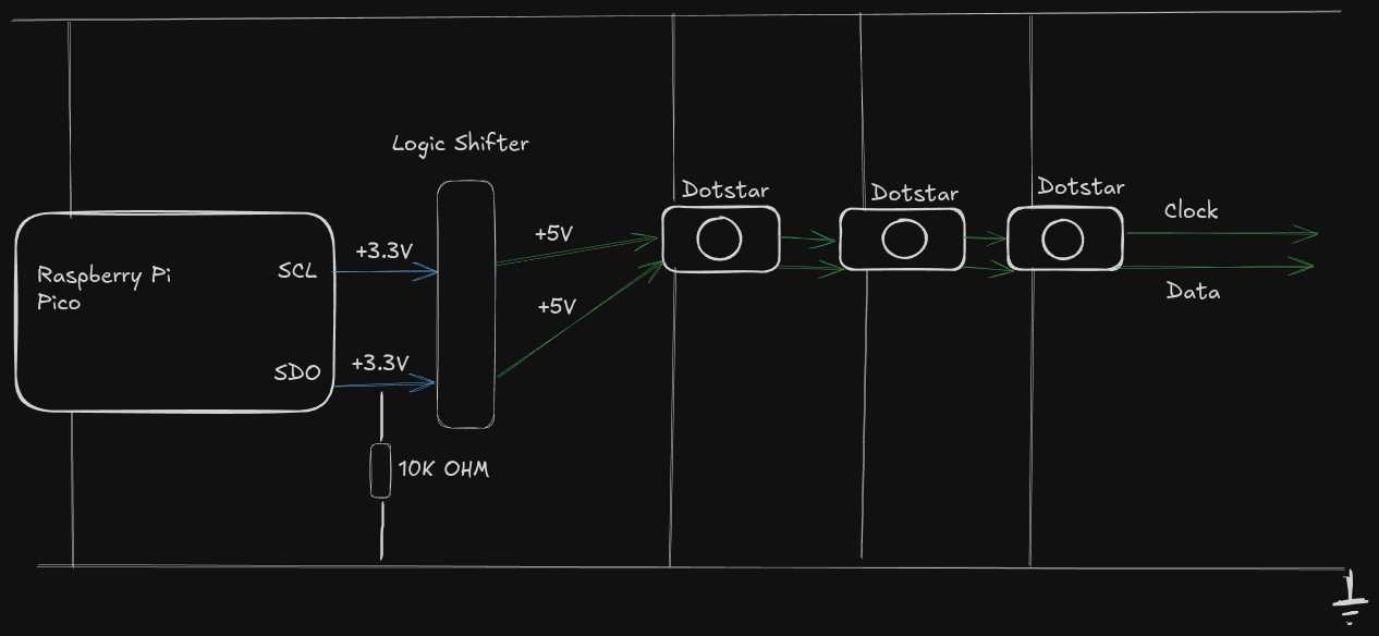
The addressable lights that I use require a 5 volt signal, while the Raspberry Pi Pico has been built for 3.3 volt signals. I have a Logic Shifter chip on this board which converts from a 3.3 volt signal to a 5 volt signal. When I say that I was probing the data line, what I was really doing was looking at the 5 volt segment of the data line. When I moved my probes to the 3.3 volt segment, the segment which connects the Pico to the Logic Shifter, the lights suddenly began working perfectly again. I moved the probes back to the 5 volt segment and again, the lights went back to solid white.
My final test was to attach probes to both the 5 volt segment and the 3.3 volt segment simultaneously and observe the signal. Once I could see clearly that the two segments carried the same data signal, I then removed the probe from the 3.3 volt segment. Immediately the 5 volt segment reverted to the broken behavior.
This is when I realized that the pull-down resistor built into the Pico must have failed. The Pico would emit a 3.3 volt signal, but without that pull-down resistor there was nothing to pull the signal back to 0. Thus, the Logic Shifter continues to read a logical 1 on the 3.3 volt segment, and thus it sends a logical 1 on the 5 volt segment. The oscilloscope itself now functioned as a pull-down resistor when I had a probe attached to the 3.3 volt segment.
Once I understood this, the solution became simple: connect a resistor between the 3.3 volt segment and ground.
When I was building the eight-bit computer project, I had to come to grips with tri-state logic. This is not trinary, but something subtly different which applies to physical wires.
For purposes of a digital signal, a wire can be in one of three states: High, Low, and Floating. When attached to the voltage source, the wire is High and this indicates a binary 1. When attached to ground, the wire is Low and this indicates a zero. But when not attached to either, the wire has no particular state. Computer circuits are designed with this in mind, and carefully timed to ensure that circuits don’t try to read a floating line.
Pull-Down resistors get involved when you want to ensure that the signal is, by default, Low. Their function is to drain current from a wire, but still allow a microcontroller to drive current into the wire to create a logical 1. If you were to think of this in terms of water and pipes, you can put water into the pipe to make it appear full. The drain lets some of the water out, but slowly enough that detectors will still read the pipe as full. This way, when you stop pushing water into the pipe, the drain will empyt the pipe without you taking any further action.
This holds true for electrical circuits as well. Voltage sensors will, by nature, drain a bit of power out of a wire that has been driven to a High signal, but generally not enough to drain the power back down to a Low signal. When I configure the Raspberry Pi Pico to treat a wire as a digital I/O wire, one of the configuration options that I set is to include this pull-down resistor so that the Pi has to only decide when to push current into the wire.
When the resistor on the Pico failed, there was no longer any mechanism to return a 3.3 volt signal back to 0 volts.
Conclusion
I had a few lessons here.
The water analogy for electricity can sometimes mislead one, but we are still pushing a fluid of electrons into a wire. They need some place to go, or anything else in the system is going to forever read that wire as being in the high voltage state.
Second, use the tools at hand, in this case a multimeter and an oscilloscope, to systematically gather data. Review what is there, and if necessary, form a hypothesis and gather more data. Electricity is logical at the scale of hobbyist digital electronics.
I still have a long way to go. The hardest part of this has never been the logic and the programming, but the challenges of attaching the control board and the handlebar buttons to my bike. Nevertheless, I persist, and I understand just a little bit more than I have in the past.